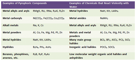
Many of the compounds encountered in organometallic chemistry are sensitive toward moisture and/or oxygen. Likewise, some organic syntheses or preparations require volatile or pyrophoric reactants. A compound is classed as air-sensitive if it reacts with O2, water, N2, or CO2. Air-sensitive compounds must be isolated from the atmosphere and handled in a controlled environment. Typically, an atmosphere of nitrogen or argon is used. This comes in a suitably pure form from a cylinder fitted with an appropriately sized regulator. As argon is more expensive than nitrogen, nitrogen is usually the preferred gas unless the compound(s) under study react with nitrogen.
Table 1. Examples of compounds that oxidize, decompose, or explode under the influence of oxygen or moisture.
Vacuum/inert gas manifold systems, commonly called Schlenk lines, are ideal for isolating and handling air-sensitive material. Their design is simple and they are straightforward to use. Combine this with specially adapted glassware with standardized Quick-Fit joints, and you have a highly modular and flexible system that enables a variety of experimental set-ups. For these reasons, Schlenk lines are routinely used for the handling and manipulation of air-sensitive compounds.
While Schlenk lines are conceptually simple, at first glance the mass of tubing and exotic glassware can be daunting for the first-time user. Here we present the basics of Schlenk line technique and in follow-up articles we will look at the various types of reaction set-up that are possible as well as the isolation and analysis of your air-sensitive product.
Basic Design and Glassware
The design of Schlenk lines varies from line to line, from lab to lab. There are, however, several key features that a Schlenk line will include (Figs. 1 and 2):
- Dual manifold
- Inert gas inlet
- Inert gas outlet via a bubbler
- Vacuum pump
- One or more cold traps for solvents
- Taps to switch between gas and vacuum
- Tubing to connect apparatus to line
The dual manifold is the main body of the Schlenk line (Fig. 1). It has two parallel glass tubes; one connected to the inert gas supply and the other to the vacuum. Taps allow switching between the gas and the vacuum lines and a Schlenk line will generally have 4–6 taps to allow multiple reactions to be performed simultaneously.
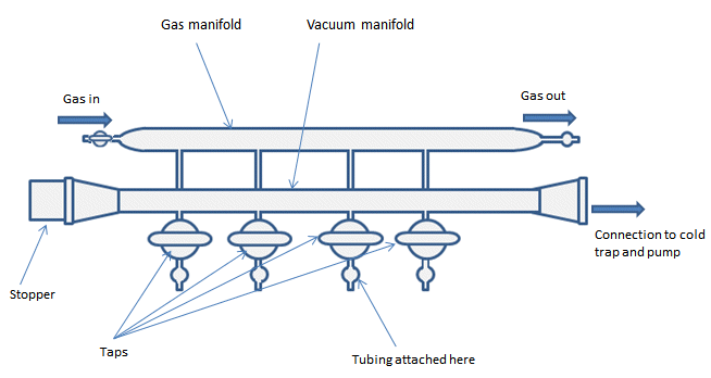
Figure 1. Basic vacuum/inert gas manifold.
High Vacuum Line or Schlenk Line?
Schlenk lines are generally used for reactions performed in solution as they lend themselves well to cannula and counterflow techniques. Manipulations involving the measurement or condensation of gases are usually performed on a high vacuum line.
Schlenk lines differ from high vacuum lines by several small features. High vacuum lines, as the name implies, have better vacuum than Schlenk lines. This arises from use of a diffusion pump instead of or in addition to the mechanical pump generally used with a Schlenk line. Schlenk lines employ flexible rubber or plastic tubing to connect the apparatus to the line, while apparatus is connected to a high vacuum line via joints that provide a better seal and vacuum.
The Inert Gas Line
The gas manifold is attached to an inert gas supply and to the gas outlet by flexible rubber or plastic tubing (Fig. 2, A). The inert gas, usually nitrogen or argon, is fed directly to the manifold, or can be passed through a drying or deoxygenation column first. The supply comes from either cylinders of compressed gas, or in the case of N2, from the run off from the main in-house liquid nitrogen tank. As argon is more expensive than N2, nitrogen is usually the preferred gas unless the compound(s) under study react with nitrogen.
The gas exits the manifold through a mercury or oil bubbler (Fig. 2). The bubbler provides a pressure release system for the line and a visible means of monitoring the general flow of gas. The bubbler should vent to the back of the fumehood or close to wherever the fumehood exhaust is, especially if it is a mercury bubbler. Mercury bubblers give a slightly higher pressure of gas in the line due to the relative higher weight of mercury compared to oil. This can be useful when it comes to filling a vessel on the line with inert gas (see part 2) as it reduces the chances of contaminating the line with air. However, due to the toxic effects of mercury, these bubblers are becoming less common.
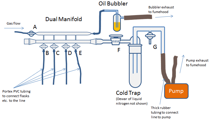
Figure 2. Complete Schlenk line set-up.
Vacuum Line and Cold Trap
The vacuum manifold is closed at one end (usually with a stopper) and attached to a pump at the other. Use of a removable stopper rather than a permanently sealed end allows access to inside of the line to facilitate its cleaning. In between the manifold and the pump there should be a cold trap (Fig 2). The trap prevents volatile or corrosive solvent vapors entering the pump and degrading the pump oil. This degradation can be harmful to pumps and shorten their lifespan, reduce their efficiency, or cause them to seize. Depending on the design of the line, the cold trap can be isolated from the vacuum line by a tap (Fig. 2, F) and opened to the external atmosphere by a tap between the trap and the pump (Fig. 2, G). This tap also allows the line to be repressurized to atmosphere once you are finished with the line.
The trap is submerged in a Dewar flask containing liquid nitrogen. The liquid nitrogen cools the trap and forces vapors and gases from the Schlenk line to condense. An alternative to liquid nitrogen is to use an acetone/dry ice combination in the trap. One trap is considered the minimum for standard Schlenk line operation. If you are intending to use the Schlenk line to evaporate solvent, two traps are recommended. Some lines have space for a second trap in series with the first, however, if the line you are using does not, a second trap can be included on the flexible tubing between the Schlenk flask and the Schlenk line. After use, the traps can be removed and the solvent allowed to thaw. The solvent can then be disposed of and the trap cleaned (see below for correct procedure for turning a Schlenk line off!).
Switching From Gas to Vacuum
On some dual manifold lines there are two taps per port or “workstation” to open the workstation to gas or vacuum. This allows individual control over the gas supply and vacuum for each line. These taps consist of a Young’s tap-type or Teflon tap that forms a seal.
Other Schlenk lines have ground-glass, two-way taps that control access to the gas and vacuum (Fig 2, B–E and Fig. 3). These taps prevent you from having both gas and vacuum lines open at the same time and feeding the inert gas straight into the vacuum pump. Ground-glass taps must be greased to ensure an air-tight seal and to make them easier to turn (see below).
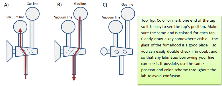
Figure 3. Side view of vacuum/inert gas manifold and positions of two-way taps for a) vacuum; b) inert gas; c) off.
Connecting Glassware to the Schlenk Line
Glassware for use in air-sensitive chemistry is similar to standard glassware, but has an additional side arm with tap with which to connect it to the Schlenk line. Two- or three-necked round bottomed flasks can be attached via an adapter. Schlenk flasks have an integrated side arm and are available in a range of sizes.
Some of the common types of glassware used are shown in Fig. 4.
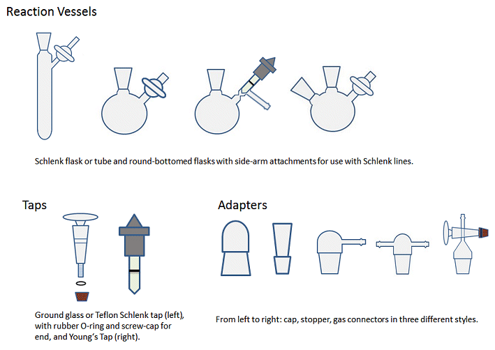
Figure 4. Common types of glassware employed in air-sensitive chemistry. The valve, tube, and ground-glass joint sizes may vary, allowing for multiple possible combinations.
The glassware is attached via flexible rubber or plastic tubing, commonly Tygon or Portex PVC tubing. The tubing needs walls at least 3 mm thick to prevent it from collapsing under vacuum. The tubes should be long enough to reach the bench or floor of the fumehood and have 3–4 cm left over. Any longer and the tubes become unwieldy and can knock pieces of glassware off the bench. If the tubing does not reach the bench or floor of the fumehood, it can be awkward to work with and may require glassware to be positioned in unusual or precarious positions in order to make the tubing reach.
The extra 3–4 cm can be useful if the line is used a lot: After a while, the constant attaching and removal of glassware to the tube will loosen the end of it and you will no longer get a good seal around the side arm. When this happens, you can cut 1–2 cm off the end without having to replace the entire length of tubing.
To connect the tubing to the glassware, gentle pressure should be applied to ease the tubing onto the connector. A wiggling or rocking motion should be used rather than a twisting motion. Wiggling the tubing provides sufficient, but not excessive force, while a twisting motion puts unnecessary force on the joint connecting the side-arm to the body of the flask. This can cause the glassware to break as you are attempting to attach the tubing which often results in you stabbing yourself in the hand with broken glassware. To help ease the tubing onto the connecting side-arm, the tubing can be heated gently with a heat gun to soften it. Alternatively, a small amount of silicon grease can be applied to the glass. Another method is to dip the end of the tubing in acetone for approximately 10 s. This will soften the tubing and allow it to stretch slightly as it is eased onto the connecting side-arm.
To remove the tubing from the glassware, it should be eased off by applying pressure with the thumb of the hand holding the glassware while the other hand rocks the tubing from side to side. Again, twisting the tubing risks broken glassware and injury so should be avoided. If the tubing is particularly stubborn and will not come off, use a sharp knife to slit the end of the tubing attached to the glassware or cut the tubing to free the glassware.
Greasing Joints and Taps
One difference between using air-sensitive techniques and air-stable chemistry is that all the ground-glass joints must be greased to ensure an air-tight seal and prevent contamination by O2, for example. In organic chemistry labs, it is often recommended to avoid greasing joints as the grease can enter the reaction mixture and contaminate the reaction and spectra. For similar reasons, joints should not be over-greased when doing air-sensitive chemistry. A fine layer of grease applied evenly is better than a thick layer that seeps out of the top and bottom of the joint. To get a thin layer, apply two stripes of grease, on opposite sides of the male joint of any glassware, insert into the neck or female joint and rotate the two parts gently to evenly distribute the grease (Fig. 5). There should be a clear, continuous film between the surfaces of the joint. Use the end of a spatula or wooden splint if you don’t want to get covered in grease.
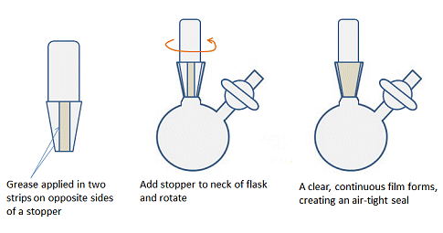
Figure 5. How to apply an even layer of grease to a joint.
Safety Considerations
Used correctly, Schlenk lines enable the use of otherwise dangerous reactants, but as with all chemistry, the use of Schlenk lines can pose some serious risks. The main risks are those of condensed gases, particularly liquid oxygen, explosion, and implosion.
Liquid Oxygen and Other Condensed Gases:
- Liquid oxygen – If a constant stream of air is pulled through the vacuum line while the cold trap is in place, oxygen will condense in the cold trap. Liquid oxygen is very dangerous and reactions violently with organic substances including vacuum grease, Teflon tape, and any organic solvents that may be in the trap. Liquid oxygen also generates a lot of pressure as it vaporizes. In the confined space of a Schlenk line, this can cause an explosion.
To avoid condensing liquid oxygen, never open the vacuum line to the air when the cold trap is in place. As a matter of good practice, air should not be sucked into the line at any point, but particularly when the cold trap is in place.
What to do if you condense liquid oxygen
Liquid oxygen is light blue in color. If you find a light blue liquid in your trap, remove the liquid nitrogen Dewar and vent the trap (for example, open tap G in Fig. 2). Close the fumehood door and leave the room. Inform your colleagues of what is happening and make sure they do not approach your fumehood. Wait 20–30 min then cautiously check to see if the liquid oxygen has evaporated. If it hasn’t, leave the area, checking back periodically until all the liquid oxygen has evaporated and it is safe to resume work.
- Other condensed gases – Some gases, such as carbon monoxide and ethylene, are easily condensed in a liquid nitrogen-based cold trap. Once the liquid nitrogen is removed, either by choice or through evaporation, the condensed liquid will convert back to a gas with an accompanying increase in pressure. Without suitable pressure release, this build up can cause an explosion.
Ensure a suitable pressure release system, such as an oil or mercury bubbler is attached to the line and the trap is vented as soon as the liquid nitrogen Dewar is removed. - Liquid nitrogen – When handling liquid nitrogen for the cold trap, or the cold glassware of the cold trap, appropriate heat resistant gloves should be worn. Cold burns can hurt just as much as regular burns.
Common Causes of Explosion:
- Use of pressurized gases – Explosion can occur if the inert gas pressure builds up in a closed system. Make sure there is a source of pressure relief in the form of a bubbler and that there is not a closed system when the gas line is open. An electronic pressure gauge or manometer can also be added to the line to monitor the pressure and provide extra peace of mind.
- Out of control reaction – A violent reaction can evolve a large volume of gas quickly. Again, ensure there is adequate pressure relief in the system, i.e., a bubbler, and that the reaction vessel is open to the line.
- Heating a closed system – Increasing the temperature of a closed system (constant volume) increases the pressure. Make sure any vessel you heat is open to the line and there is pressure relief in the form of a bubbler attached to the line.
Common Cause of Implosion:
- Cracks in glassware – Any weakness in the glassware, such as a star crack, can cause it to fail under vacuum. If you notice a crack in a vessel, do not use it. Many cracks can be repaired by a glassblower, so do not throw cracked glassware away without discussing it with your glassblower first.
Getting Started
To avoid the potential dangers discussed above, Schlenk lines need to be started up and shut down in a specific order.
Turning a Schlenk Line On
It can take about 30 min to start and purge a Schlenk line before its first use, so make sure you allow yourself enough time. The following steps assume there is no gas flow through the system. If the gas is already on, skip steps 3–5.
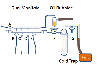
Figure 6. Schlenk line before it is turned on.
- Check all taps are greased. If a tap feels dry or hard to turn, remove it and apply a light coat of suitable high vacuum grease to the tap, avoiding the holes which can become blocked with grease. Replace the tap and turn it several times to evenly distribute the grease. There should be a clear, continuous film between the surfaces.
- Check tap A is open and taps B–E and G are closed (Fig. 6).
- Open the gas supply. If you are using cylinders of compressed gas, check the cylinder has sufficient N2 or Ar before you begin and use standard cylinder safety and operating procedures.
- Adjust gas supply so that the exhaust bubbler has a flow rate of about one bubble per second. If there is no gas flow through the bubbler, turn off the gas supply, vent the manifold by opening tap G or one of taps B–E, and repeat steps 1–4.
- Purge the gas line for 20 min or more. Purge time can be reduced with a faster flow rate, but be careful not to increase the gas flow rate so that oil is blown out of the bubbler. Don’t forget to turn the flow rate down once the line is purged!
- While the gas line is purging, check the cold trap. Trap should be empty, clean, dry, and the connecting joint should be well greased.
If it is not, empty the trap into the correct waste solvent container and rinse with acetone or other suitable cleaning solvent. Leave it to dry for several minutes or blow a stream of nitrogen or air into the trap to encourage solvent to evaporate. When it is dry, grease the joint at the top with suitable high vacuum grease. Re-attach the trap and rotate it once or twice to evenly distribute the grease across the joint and provide an air-tight seal. There should be a clear, continuous film between the surfaces. Clip trap in place – Do not rely on the vacuum to hold the trap in place. - Place an empty Dewar flask under the trap so that the top of the flask is 1–2 cm below the bottom of the trap’s joint (Fig. 7).
- Check tap F is open and close tap G (Fig. 6).
- Turn on pump and allow it to warm up for 3–5 min.
- Fill the Dewar flask with liquid nitrogen.
- Cover the top of the flask with a towel, piece of cloth, or polystyrene block shaped to fit.
- You are now ready to begin work.
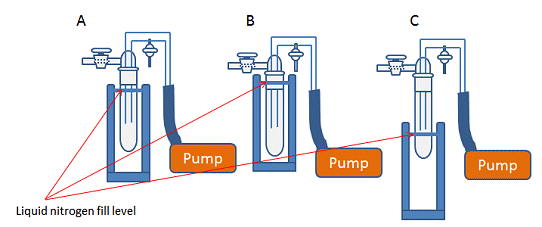
Figure 7. A) Correct position of Dewar flask and liquid nitrogen fill level for cold traps. B) Dewar flask and liquid nitrogen too high, which risks freezing the grease in the joint, breaking the seal and making the trap hard to remove. C) Dewar flask and liquid nitrogen too low, leading to incomplete condensation of gases and potential damage to pump.
Turning Off a Schlenk Line
- Make sure all vessels attached to the line are under nitrogen.
- Switch off pump and immediately remove the Dewar of liquid nitrogen.
- Vent the vacuum line by opening tap G (Fig. 6).
- Switch off gas. If someone else is going to use the Schlenk line after you, or if you are leaving a vessel open to nitrogen, only reduce the gas flow rate rather than turning it off completely.
- Remove cold trap carefully – Cold glassware can burn or get stuck to your skin.
- Allow the collected solvent to thaw. This can be done overnight if it is the end of the day. Dispose of the liquid solvent and clean the trap ready for next time.
Summary
Air-sensitive techniques and equipment can look daunting, but the usefulness of the Schlenk line cannot be denied. The two interconnected lines of the manifold provide a simple way to evacuate a flask and refill it with an inert atmosphere if the safety considerations are taken into account by performing the steps in the correct order.
- Next month: The basis of all Schlenk line work, the evacuate-refill cycle, and how to dry and/or degas solvents.
- See all Tips and Tricks on air-sensitive chemistry
Do you have any tip or tricks for handling air-sensitive compounds? Share them in the comments section …


